    
Tech808
Moderator
Username: Tech808
Post Number: 6384
Registered: 8-2002

| | Posted on Wednesday, July 20, 2005 - 12:21 am: | 


|
The  COBRA 150 GTL DX COBRA 150 GTL DX
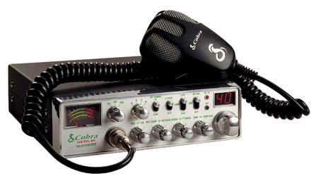
COPPER PART:C90-07010
AM/FM 10 METER MOBILE AMATEUR TRANSCIEVER
Complete Specifications, Modifications, and Non - Technical Review.
By
Lon ~ Tech808 ~ N9OSN ~ CEF808
General Specifications
| Emission Modes | AM/FM | | Antenna Impedance | 50 ohms | | Antenna Connector | Standard SO-239 type | | Microphone | Cobra M73SL (Plug-in dynamic with Press-To-Talk switch and coiled cord | | Frequency Range Stock | 28.0 to 29.7 MHz | | Frequency Range (after conversion) | 26.065 to 29.695 | | Frequency Control | Phase-Lock Loop (PLL) Synthesizer | | Frequency Stability | 0.005% | | Operating Temperature Range | -22 F to 122 F (-6 C to +50 C) | | Input Voltage | 13.8 V DC nominal / 15.9V max Positive or Negative Ground | | Currant Drain | Transmit: 3.0A / Receive (squelched) 0.5A / Receive (maximum audio output) 1/2A | | Weight | 4.8lbs | | Dimensions / Size | 2-3/8 (H) x 7-7/8 (W) x 9-3/4 (D) | | Meter | (3 in 1)Illuminated-indicates relative output power / received signal strength and SWR | | Built in Speaker | 4 watts |
Transmitter Specifications
| Power Output | Low ~ 4 watts / High ~ 15 Watts | | Final Transistors | Mitsubishi RD16HHF1 Silicon Mos Fet (x2) Rated at 16 watts at 30 MHz | | Frequency Tolerance | 500Hz | | Frequency Response | 300 to 3000 Hz | | Transmit Distortion | 2% | | Spurious Harmonic Emission | -65dB | | Output Indicators | Meter shows relative RF output power and SWR. Transmit LED glows red when transmitter is in operation | | Antenna Warning LED | Glows red when SWR is greater than 3.0 |
Receiver Specifications
| Sensitivity | AM:0.5 µV for 10dB S/N, FM:025 µV for 12 dB S/N | | Audio Frequency Response | 300 to 3000 Hz | | Maximum Signal to Noise Ratio | 45dB | | Image Rejection | 75 dB | | Adjacent Channel Rejection | 65 dB | | RF Gain Control (AGC) | 40 dB - adjustable for optimum signal rejection | | Squelch | Adjustable - threshold less than 0.5µV | | Automatic Noise Limiter (ANL) | Switchable | | Noise Blanker (NB) | Switchable | | Receive Indicators | Meter shows relative signal strength / Receive LED glows green when receiving a signal. |
PA System
| Power Output | 4 watts into PA speaker | | Speaker for PA (Not Supplied) | 8 ohms |
External Speaker
| Power Output | 4 watts into a PA speaker | | External Speaker(Not Supplied) | 8 ohms |
Standard Features / Controls / Connectors on Radio.
Front Panel
* Analog Meter
* PA/AM/FM Control Selector Control
* Band A/B/C/D/ Slector Control
* RF Power Hi/Low Switch
* +10kHz / Off Switch
* NB/ANL Off Switch
* Dual 7 Segment Frequency Display
* Microphone Connector (Standard 4 Pin)
* Off/On Volume Control (Center Knob) / Squelch
(Outer Ring)
* Microphone Gain (Center Knob) / RF Gain (Outer Ring)
* Talk Back (Center Knob) / Echo (Outer Ring)
* Dim (Center Knob) NightWatch & Meter / Not Channel Display / SWR Cal (Outer Ring)
* Antenna Warning Indicator
* Frequency Selector
Back Panel
* External Speaker Connector
* 2 Wire T-Fitting Power Cord Connector Wire
(No Standard Plug in Type Connector)
* SO-239 / Antenna Connector
* Frequency Counter Connector (FC390 / FC347 Type)
Introduction:
The Cobra 150 GTL DX is programmed for the 10 Meter Amateur Band out of the box, and covers a range of 28.000 - 29.700 MHz.
The frequency range can be extended for Export Use in 4 Band segments each containing 80 Channels except Band D which will contain 76 Channels.
Stock 10 Meter Frequency Coverage:
This mode is pre-set to 4 Bands with coverage of the 10 Meter Band from 28.000 MHz to 29.700 MHz.
A-Band ~ Channels 1 thru 49 = 28.000 thru 28.495
B-Band ~ Channels 50 thru 99 = 28.500 thru 28.995
C-Band Channels 00 thru 49 = 29.000 thru 29.495
D-Band ~ Channels 50 thru 70 = 29.500 thru 29.700
Export Conversion
Export / Converted Frequency Coverage:
Channel Display:
The Channel Display has visual indicators located on each side of the Channel Number/Display to indicate the Band Segments and the "A / Alpha" Channels.
The Band Segment Dot is displayed to the LEFT of the Channel Display and the A / Alpha Channel Dot is displayed to the RIGHT of the Channel Display and will look like this: .20.
This mode has 8 Bands divided into 4 Bands with switch positions on the radio marked A/B/C/D
Each band has two (2) 45 channel frequency blocks for each letter A/B/C/D
For example: Band "A" would start on the lower frequency segment 1~40 and then continue to the next segment when channel 40 is passed.
The channel display will show a small Red (.) dot on the Left Side of the Channel Display indicating that the radio is in the UPPER SEGMENT of the 2 Bands.
The Channel Display will look like this ~ .20
The Cobra 150 GTL DX also has "Continuous" coverage of each Band by NOT skipping the "A" channels between channel 3, 7, 11, 15, and 19.
As you reach Channel 3 the next Channel up will display the number 3 again with a small dot on the RIGHT SIDE of the 3.
The Channel Display will look like this: 3.
This will represent Channel: 3A
After Conversion Frequency Coverage:
A-Band- 26.065 - 26.505
.A-Band- 26.515 - 26.955
B-Band- 26.965 - 27.405
.B-Band- 27.415 - 27.855
C-Band- 27.865 - 28.305
.C-Band- 28.315 - 28.755
D-Band- 28.765 - 29.295
.D-Band-29.305 - 29.695
Microphone Wiring
Pin #1 ~ Ground
Pin #2 ~ Microphone Audio
Pin #3 ~ Transmit
Pin #4 ~ Receive
Modifications
I have added the Tune-Up Information that I have to the Copper Modification List.
At the time of my writing this Review I know of No Other Modifications for this radio.
Should any Modifications or Tips become avialiable I will keep everyone updated.
PROS & CONS
Pros
* Limited 2 Year Factory Warranty
* 2 ~ Mitsubishi RD16HHF1 Silicon MOSFET Power Transistors: Rated: Pout>16W, Gp>16dB @Vdd=12.5V,f=30MHz (Replaces older style 1969 finals.)
* Power in bench testing with power switch set to HI produced a 15 watt dead key swinging to 50 watts PEP. 
* Toshiba 80 Pin TMP87PP21DF Microprocessor.
* Super Heavy Duty 10 gauge Power Cord with Automotive 10 Amp large blade type fuse.
* 2-1/8" x 3" x 7-3/4" Single Piece Solid Aluminum Heat Sink.
* SMT Components.
* PFM-0089A-BB Mother Board
* External Frequency Counter Connector located on back panel (ie: FC347 / FC-390 Type) Located under SO-239 conector.
* Style Cobra M73SL Microphone (Stainless Grill)
* 1/4" Larger / Taller Analog Meter
Cons
* This radio should be called an 8 Band Radio as you will have 8 Bands/Groups of channels after Conversion.
You will have 2 Bands/Groups of channels on each of the 4 Bands A thru D.
* No Variable Power Control just a High/Low Power Switch.
FINAL COMMENTS
While this Cobra 150 GTL DX looks larger than the older cobras it is the same size as only the SWR/Watt Meter is slightly larger with new style control knobs.
I would personally suggest adding a FC347 or FC390 Frequency Counter as the Frequencies / Channels do not match the standard 3/6/8/10 or 12 band Frequency/Channel Charts.
Respectfully Submitted,
Lon
Tech808
N9OSN
CEF808
|

