| Author |
Message |
    
Coyote
Intermediate Member
Username: Coyote
Post Number: 192
Registered: 11-2004

| | Posted on Wednesday, April 06, 2005 - 7:45 pm: | 


|
I have a Boomer which uses two 6JU6 tubes. It is of course designed for use on 6 and 10 meter. Will it need to modified for use on 11 meter? If so, what will need to be done? Thanks all. |
Scrapiron63
Advanced Member
Username: Scrapiron63
Post Number: 811
Registered: 12-2001
| | Posted on Wednesday, April 06, 2005 - 11:26 pm: |
|
That sounds like a Big Boomer. I thought all those old tube type boomer amps would work on 11 meter. Have you tried to see if it would.
|
Coyote
Intermediate Member
Username: Coyote
Post Number: 193
Registered: 11-2004
| | Posted on Thursday, April 07, 2005 - 5:30 am: |
|
Scrapiron, I dont know if its a big boomer, its only rated for up to 80 watts. I thought it would work too. I have tried to use it but everyone say's it has a hum and distorts my voice. Maybe it has another problem. I have dropped my DK to 3 watts with no change. I thought that maybe since it was designed for 6 and 10 meter that it was possible that something needed to be done to it for 11 meter operation, although it could be it has other problems. Guess I should have stated all this originally.  |
Scrapiron63
Advanced Member
Username: Scrapiron63
Post Number: 812
Registered: 12-2001
| | Posted on Thursday, April 07, 2005 - 11:06 am: |
|
Coyote, I guess the kris big boomer I was thinking about just had one tube. Just dug thur my old stuff and found this instruction manual. Does it look like your's.
http://img.photobucket.com/albums/v208/Familystuff/boomer.jpg
Maybe Mr 2600 will get in on this thread, he knows these old tube amps. Sounds like you've got something wrong in the power supply, letting the ac hum into your TX. But an easy thing to check first would be the tubes, could be one bad.
This manual has a parts list and schematic if you need it. BTW, it's dated 1971 if you wonder about it's age, so it's old enough to vote or buy a drink. 
I may be wrong, but I don't think the Kris amps were ever made for 6 and 10 meter, they might have claimed that. Probably not many hams would use something called a "Boomer" anyway, that sounds too much like CB.  |
Coyote
Intermediate Member
Username: Coyote
Post Number: 194
Registered: 11-2004
| | Posted on Thursday, April 07, 2005 - 2:27 pm: |
|
Thanks Scrapiron, I can't look at that link at the moment, I'm at work and our server won't allow me to go there. I'll check it out when I get home and let you know if thats the one or not. The plate on the back of the amp say's it is designed for 6 and 10 meter, but that may have just been a way around uncle charlie back then so it could be sold in the US. I figured if it would work on 10 meter that it "should" work ok on 11 meter as well, someone correct me if needed.
Someone else on the air mentioned a bad power supply, and possible polarization of the house current at the plug too????, so I'm not sure which way to go. I know how old tube stuff can pick up things like that and a small hum can turn into a big one when it gets in an amplifier.
I was just curious that if it was intended for 10 meter if it would need modification or not, and then I would go from there. Would like to get it fixed, its not like its a big powerhouse or anything, but might just be enough to get the signal out when I need to.  |
Coyote
Intermediate Member
Username: Coyote
Post Number: 198
Registered: 11-2004
| | Posted on Thursday, April 07, 2005 - 8:16 pm: |
|
Scrapiron, yeah.. thats what it looks like. I have the manual, its available on line. Its not much of a manual, but does have a parts list and schematic. |
2600
Advanced Member
Username: 2600
Post Number: 533
Registered: 7-2002

| | Posted on Saturday, April 09, 2005 - 2:34 am: |
|
Hi Coyote,
You said you got reports of hum and distortion on your signal when the Boomer was keyed. Sure sounds like C9 and C10, the filter capacitors for the high voltage have finally figured out just how old they are.
Electrolytic capacitors aren't meant to last for 20 years, let alone 30-plus.
The manual lists a "30 uF 500 Volt" for C9 and C10. If memory serves, the easier-to-get 450-Volt parts won't quite cut the mustard in a Boomer. Puts a little too much voltage on them. The two filters C9 and C10 are wired in series, to split the 950-Volt (approx) supply voltage half-and-half.
The 500-Volt filters cost more and are not as widely available. If you have a look underneath, I'll predict that they look distressed, with cracked or swollen rubber end-cap insulators, maybe some brown dusty stuff that has dried on surfaces when the liquid inside leaked out.
One trick that works is to use three capacitors in series in place of the original two. Each one need not be rated for more than 350 Volts each this way. If the 450-Volt caps are easier to find, they work fine this way. Just can't get by with (only) two of the 450 caps in series. Almost, but not quite. If you use a series string of three caps, you need a higher capacitance value than the listed 30 uF. If you use a string of three parts, the minimum capacitance will be 47 uF each. Higher is okay, just so long as all 3 have the same capacitance rating.
If you change the filters, you really should change the bleeder resistors at the same time. They show a 100k 2Watt in parallel with each filter. That one will get too hot. If you use a 2-Watt resistor, 220k is a better choice than 100k. We use a 5-Watt part when a 100k resistance is needed. Those are harder to find than a 220k 2 Watt. If you use three capacitors in series to get your total voltage rating above 1000 Volts, you will need three bleeder resistors, one for each filter in the series string. They must all 3 be the same value. Exact value isn't critical. Any resistance from 470k down to 180k should be good enough, just so long as ALL THREE have the same resistance. The bleeder resistors serve two purposes. First, to bleed off the stored charge, when the power is turned off. A safety issue. Second, is to divide the DC voltage equally across the capacitors. To do this both, (or all three) bleeders have to have the same resistance value.
I looked at Antique Electronic Supply, but no 500-Volt parts there. All the other sources I find have a high minimum order.
Bummer.
73
|
Coyote
Intermediate Member
Username: Coyote
Post Number: 202
Registered: 11-2004
| | Posted on Saturday, April 09, 2005 - 10:01 am: |
|
Hi 2600, glad you showed up. Well, heres what I found. Of the two filter capacitors, one has already been replaced at some point. It is a metal can type. The other one looks like an original and while it doesn't appear to have leaked, there is a small bubble on part of + side of the insulator cap. Thank you 2600, this is where I'll start and replace these component's. Thanks a million! |
Coyote
Intermediate Member
Username: Coyote
Post Number: 203
Registered: 11-2004
| | Posted on Sunday, April 10, 2005 - 4:12 pm: |
|
2600 or anyone else that can answer this. I found 40mfd 500v capacitors, can these be used in place of the 30mfd 500v ones? Anyone? |
Coyote
Intermediate Member
Username: Coyote
Post Number: 205
Registered: 11-2004
| | Posted on Sunday, April 10, 2005 - 9:58 pm: |
|
Ok, I think I found them, is this it?
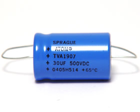
Thanks
|
2600
Advanced Member
Username: 2600
Post Number: 537
Registered: 7-2002
| | Posted on Monday, April 11, 2005 - 1:47 am: |
|
Hi Coyote,
In general, a higher rating, either for the voltage OR the capacitance value is okay in a power supply filter circuit.
The 40uf will work pretty much the same. If you have a peak-reading wattmeter, the larger filter MAY show a slightly higher peak output from the amp than it will with the stock part, but never enough to matter.
Because the actual measured value on this type of part has a very "loose" range of tolerance, it's not uncommon for a part marked "80" uf and one marked "100" to be the exact, same part on the inside. Different printing on the wrapper, but since the acceptable range of actual value overlaps for both parts, they may use the 100, marked as an "80 uf". You might very well find that the "30" and the "40" are the same way, if you bought some of each.
The one in the pic should be an exact replacement, from the looks of it. Just make sure to use two of the SAME part, whatever the capacitance value.
I still favor replacing the two bleeder resistors at the same time. The originals may or may not be trustworthy. If you measure each one in the amp with an ohmmeter, remove the old filters first. They can make the bleeder resistors hard to measure, if left in the circuit. If both bleeders are within about 10% of the same resistance value, they may be okay.
Just replacing the bleeders anyway is cheap insurance, compared to the price of the filters, and the aggravation of changing them twice.
It would also NOT hurt to check the eight rectifier diodes, just to be sure that none of them were damaged when the filter went bad. Sometimes a filter that fails can put a current surge through the rectifier diodes. This is a less-common cause of hum problems, but you wouldn't want to assasinate your new filters with a damaged rectifier diode, either.
73
|
Coyote
Intermediate Member
Username: Coyote
Post Number: 207
Registered: 11-2004
| | Posted on Monday, April 11, 2005 - 9:41 am: |
|
Thanks again 2600, I found the ones in the pic for $5.75 apiece and will be getting two new ones real soon and I will just replace the resistors at the same time, probably order them from the same place when I order the caps. The way its all soldered they will probably already be de-soldered when I remove the old caps anyway. Might as well put new ones in at that time.
Is there a way to check the diodes by visual checking, meaning, would there be any external indication, or do these need to be checked from the get go with a meter? I have a good meter so its not a problem.
Also half thinking about getting a couple new tubes for it as well, I found them fairly cheap, never hurts to have a couple spares for the future.
Might as well fix it right the first time and have it around another 30+ years. 
(thinking 2600 should be "Tech2600", what about it Copper?) |
Grnlght
New member
Username: Grnlght
Post Number: 2
Registered: 2-2014
| | Posted on Friday, October 14, 2016 - 1:12 am: |
|
Figured i would post to this thread and not make a new one... I have a big boomer by kris e-caps replaced and diodes 1500volt 1amp at idle not transmitting one of the diodes after a bit will short and blow the fuse |
Grnlght
New member
Username: Grnlght
Post Number: 3
Registered: 2-2014
| | Posted on Friday, October 14, 2016 - 11:07 pm: |
|
Correction when the tx standby switch is moved to standby that is when it kills the diodes and blows the fuse other than that it seems to work fine |
|

