| Author |
Message |
    
Admin
| | Posted on Sunday, January 20, 2002 - 6:46 pm: | 


|
Imax 2000 Exposed
by Tech 833
After dissecting the Antron 99 antenna and discovering that its advertising claims were horribly over-exaggerated, I became curious about other fiberglass 'wonder' antennas. An opportunity to dissect the Imax 2000 presented itself, so I accepted.
The first thing you notice about the Imax 2000 is that it is LONG! I measured the copper wire elements after they were removed from their fiberglass radomes:
Bottom section: 80 inches
Middle section: 94 inches
Top section: 96.5 inches
That makes the total radiating element length 270.5 inches. Using 27 MHz. (CB) as center frequency (which this antenna was designed for), that makes the Imax 2000 a 0.640 wavelength antenna. (A 5/8 wave antenna is 0.625 of one wavelength). I was very surprised to find that the Imax 2000 is not a 5/8 wave as advertised. The Imax 2000 is actually a .64 wave! The .64 wave is one of the best kept secrets in CB and 10 meter antennas. Not since the Super Penetrator 500 Gold has there been a .64 wave antenna widely available. A .64 wave antenna is the highest gain single element design there is with 0.4 dB more gain on the horizon (free space) than a 5/8 wave element.
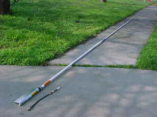
Photo 1 | In photo 1 I have the antenna laid out with the insides alongside the fiberglass shell it was once housed in. Removing the insides from the 2 lower sections was accomplished with a Dremel tool and a cutting wheel. Removing the insides of the upper section required a planer and systematically shaving away fiberglass until I got down to the copper wire inside. I had to determine if there were any coils or anything inside the top section. Instead, it's just a length of stranded copper wire. However, with a .64 wavelength element, adding coils would distort the otherwise clean pattern, so I was glad to find just the wire. The only thing that could improve this antenna would be a counterpoise (ground planes). More on this later. |
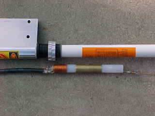
Photo 2 | In photo 2, you see what is inside the lower section and how the tuning rings affect the coil's tuning. Except for the lower 2 feet of the Imax 2000, all the rest of the antenna contains nothing more than a straight piece of #14 bare copper wire. An upgrade from the A99, the Imax 2000 uses RG-213 coaxial cable which connects to the SO-239 connector in the bottom of the mounting pipe and to the coils of the matching section. Just to the right the outer coil is the brass outer 'plate' of the coupling capacitor. The 'twin ring' match works by moving the metal rings closer or further away from the outer coil which changes the inductance and therefore, the resonant frequency of the radiating element. |
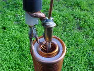
Photo 3 | In photo 3, you can see how the coaxial cable connects to the Imax 2000 feedpoint at the bottom of the coils. There was a small plastic spacer that I removed for the clarity of the photo. Here, you can see that the soldering job was excellent and very electrically secure. Using the brass crimp sleeve seen here helps add a mechanical strength to the solder joint which will help the antenna maintain it's electrical integrity through vibration and temperature fluctuations. The inductance tuning coil in the Imax 2000 is much smaller (and less lossy) than the Antron 99 antenna. The Imax 2000 uses 10 turns of #14 enameled copper wire. |
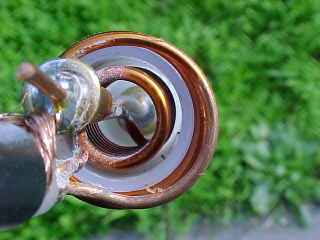
Photo 4 | Photo 4 gives you a good view of how the inner impedance matching coil fits inside the outer tuning coil. With the radiator length being .64 wave, the impedance at this point is extremely high. The inner coil provides a 50 ohm tap on the driven element, while the outer coil cancels out the capacitive reactance created by the coupling capacitor and the capacitance at the fed end of the radiator. One of the big secrets to getting a wideband antenna, which many other antenna makers apparently ignore, is completely canceling out the reactance. Even a few ohms of reactance at the feedpoint will greatly reduce the bandwidth. By tuning the reactance to zero, the SWR will be very low over a wide frequency range. |
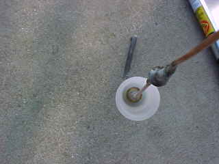
Photo 5 | Photo 5 provides a look inside the coupling capacitor viewed from the radiating element end. If you look carefully, you will be able to see the excellent soldering job from the copper wire to the brass inner 'plate' of the capacitor. Here, as in the Antron 99, you also see another brass crimp sleeve used to strengthen the capacitor plate stub to radiator element solder joint. The Imax 2000 is built much better than the Antron 99 reviewed in an earlier article. The attention to solder joints was much better in the Imax 2000, and I was very pleased to see this attention to detail. It makes for a much 'quieter' antenna. |
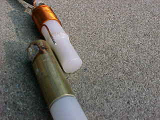
Photo 6 | In photo 6, you get a look at the nylon spacer which forms the 'dielectric' of the coupling capacitor. I had to use a great deal of heat to remove the press fit brass sleeve, so some melting of the nylon is evident. There is NO WAY this would come apart by accident! Like the Antron 99 coupling capacitor, when measured with a capacitance meter, I measured a value of 4pF for each end. That's measured radiator-to-sleeve and again from ground-to- sleeve. The Imax 2000 radiating element is capacitively coupled rather than connected directly to the coax to isolate the antenna base from high voltages in case the installer happens to drop it across power lines and the radiator happens to make contact with high voltage. |
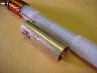
Photo 7 | Photo 7 shows the inside of the capacitor coupling unit with the components alongside each other for spacing reference. A brass cylinder inside the nylon forms the inner conductor or 'plate' of each end of the coupling capacitor. The brass cylinders do not touch each other end to end, there is a small space left which acts like a spark gap in the case of lightning strike to take the charge straight to ground. For a more detailed idea of how this works, check out the schematic diagram below. |
Schematic 1 |
CLOSING STATEMENTS: In summary, the Imax 2000 is a very well built and well thought out antenna. It's ironic that the Antron 99 paved the way for this antenna, but the Imax 2000 is head and shoulders above the Antron 99 in engineering practice. So much additional inductance coil is needed in the Antron 99 to get the highly capacitive 1/2 wave element tuned. However, in the Imax 2000, with the .64 wavelength element, the capacitance is much lower, which requires much less inductance to tune it out. Therefore, much less coil is required to tune the Imax 2000 to resonance, which greatly reduces the coil losses.
So what is the TRUE gain of the Imax 2000? Assuming a .64 wave shunt fed dipole in free space, minus the losses associated with the series capacitance and inductance, and minus the necessary counterpoise, according to my math, the Imax 2000 has 2.9 dBi gain. That is to say, the Imax 2000 has 2.9 dB gain on the horizon over an isotropic radiator. Referenced to a center fed 1/2 wave dipole, which is the industry standard, the Imax 2000 has a gain of 0.8 dB. This could also be stated as 0.8 dBd gain. Although adding the Antron GPK-1 ground plane kit will not add much gain to the Antron 99, the ground plane kit would add significant gain on the horizon for the Imax 2000. A .64 wavelength radiator is much more efficient and will have a much lower angle of radiation (keep the signal down on the horizon instead if wasting it up in the sky) with a proper counterpoise system. Adding the GPK-1 to the Imax 2000 (according to my math and previous .64 wavelength test range plots) will result in a 0.3 dB gain improvement. This will bring the Imax 2000's actual gain up to 3.2 dBi (or 1.1 dBd).
CONCLUSION: The Imax 2000 will easily outperform the Antron 99 and other 1/2 wave antennas like the popular 'Ringo'. Adding the GPK-1 ground plane kit will provide a significant improvement in gain on the horizon, which will noticeably improve local communications. With the wide availability and reasonable price of the Imax 2000, it is easy to suggest this antenna to the 10 and 11 meter enthusiast who desires top performance, and a more visually low profile fiberglass antenna.
-Tech 833 |
|

