    
Tech808
Moderator
Username: Tech808
Post Number: 16832
Registered: 8-2002

| | Posted on Wednesday, April 29, 2009 - 9:14 am: | 


|
CONNEX
CX-33 TLM3
AM/FM 10 Meter Mobile
Radio with
TTF Display & MP3 Player
Complete Specification's, and Non - Technical Review.
By
Lon ~ Tech808 ~ N9CEF
NOTE!
Reading the Owner's Manual
BEFORE
connecting this radio to powe is a
MUST!
FRONT PANEL CONTROL'S:
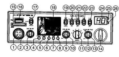
01: MICROPHONE JACK
02: RF GAIN CONTROL
03: MIC GAIN CONTROL
04: DISPLAY SELECT ~ (6) Position
05: DIMMER CONTROL ~ (6) Position
06: REVERSE
07: PLAY/STOP SWITCH
08: NEXT/FORWARD SWITCH
09: SQUELCH CONTROL
10: ON/OFF/VOLUME CONTROL
11: BAND SELECTOR ~ (6 Bands after Conversion)
12: TIME CONTROL
13: ECHO/TALKBACK CONTROL
14: CHANNEL SELECT
15: SD Port
16: USB Port
17: METER/AUDIO/PHOTO SWITCH:
18: TFT LCD DISPLAY
19: MP3/RADIO
20: AM/FM/PA SWITCH
21: NB/ANL/OFF SWITCH
22: AM/FM/PA SWITCH
23: CH19/NORMAL SWITCH
24: CHANNEL DISPLAY
25: TX/RX LED
26: ANT LED
REAR PANEL CONTROL'S:
01: ANTENNA: This jack accepts 50 ohms coaxal cable with a PL-259
02: AUX OUTPUT: This Stereo 3.5mm jack, Supply 200 ohms 2V Output
03: DC POWER: 13.8 V DC power cable with built in fuse.
04: RIGHT SPEAKER: This Jack accepts 4 to 8 ohm's, 5 Watt's external speaker.
05: LEFT SPEAKER: This Jack accepts 4 to 8 ohm's, 5 ~ Watts external speaker.
06: PA SPEAKER: (8 ~ Ohm's / 5 ~ Watt's) to this jack.
MICROPHONE WIRING:
PIN #1 ~ AUDIO
PIN #2 ~ AUDIO LEAD
PIN #3 ~ TRANSMIT
PIN #4 ~ RECEIVE
GENERAL SPECIFICATION'S:
| Model: CX-33TLM3 | | Channels: 240 | | | | Frequency Coverage: Stock 28.015 ~ 28.465 MHz | | Frequency Coverage Expanded: 25.615 ~ 28.305 | | Emission: AM/FM | | Frequency Control | Phase-Lock Loop (PLL) | | Frequency Stability | 0.001% | | Temperature Range | -30°C to +50°F | | Antenna Impedance | 50 Ohms | | Input Voltage | 13.8VDC | | Size | 7-7/8(W)x10-3/4(D)x2-3/8(h) | | Weight | 5.0 lbs |
TRANSMITTER SPECIFICATION'S:
| RF Power Output | AM / FM 10W (H) x 4W(M) x 1W(L) | | 2 ~ IRF520 Duel Finals | With 2SB827 Modulator/Regulator | | Spurious Emissions | -50db | | Audio Distortion | 10% | | Frequency Responce | 300 to 2500Hz | | Microphone | Dynamic |
RECEIVER SPECIFICATION'S:
| Sensitivity for 10dB (S+N/N | 1.0uV | | Squelch | 0.5uV | | Image Rejection | More than 65dB | | AGC Figure of Merit | 100 mV for 10dB Change in Audio Power Output | 2.5W @ 10% Distortion | | Audio Responce | 300 to 2500 Hz | | Audio Input | 2V @ 10K ohms | | AUX Output | 2V @ 200 ohms |
Frequency Expansion:
Step #1 ~ With radio facing you Upside Down Remove 5 screws from Bottom / Speaker cover & carefully set next to radio.
Step #2 ~ You will then see a Sub Board held in place by 4 screws.
Step #3 ~ Loosen the rear (2) screws and Remove the Front (2) screws and set aside.
Step #4 ~ In your radio box you will find a (6) wire stub with (green/yellow/orange/red/brown/black) wires with heat shrink on one end and a 6 Pin Female Plug on the other end.
Step #5 ~ Carefully lift the front of the board UP and you will see (IC2) ~ (6) pins sticking up on the LEFT front side of board that fits under the board you removed the (2) screws from.
Step #6 ~ Install the (6) wire stub with (green/yellow/orange/red/brown/black) on IC2 the empty (6) pins (IC2) sticking up.
Step #7 ~ Re-install the 2 screws in the board and tighten the (2) screws you loosened.
Step #8 ~ Just to the (Front Right) of the (6) pin's / (IC2) where you installed the Frequency Module you will see (2) bare pins sticking up marked JP3.
Step #9 ~ Carefully "SHORT" these (2) pins while Turning the Power (ON) to the radio.
Step #10 ~ This has now converted your radio to the Expanded Mode.
Step #11 ~ You can now remove the (6) pin Module or leave it in place.
Step #12 ~ Replace speaker side cover & screws.
Step #13 ~ Frequency / Expanded Mode Conversion is now Complete. 
RESTRICTION's & LIMIT's:
#1 ~ The USB input slot will Only handle (1 ~ GB) Maximum.
* If this limit is excedded the radio will shut down and you will need to remove the power cord on the rear panel to restore it.
#2 ~ The SD input slot will Only handle (2 ~ GB) Maximum.
* If this limit is excedded the radio will shut down and you will need to remove the power cord on the rear panel to restore it.
#3 ~ Your picture's Must also be in JPEG format for them to be displayed on the TFT screen.
Lon~Tech808
N9CEF~EN50mk
CEF#0808~CVC#0002
|

