| Author |
Message |
    
Tech833
Moderator
Username: Tech833
Post Number: 1759
Registered: 8-2002
| | Posted on Wednesday, October 07, 2009 - 12:58 am: | 


|
Penetrator P500 Restoration
By Tech 833
Last time, we reviewed the Hy-Gain Penetrator P500 antenna, and found out what makes it work. As mentioned in the last article, the Penetrator hasn�t been made in about 15 years, and is no longer commercially available new. For those who want to own a Penetrator antenna, your only hope is to purchase a used one.
Since the Penetrator was such a huge-seller, there are still plenty of them around. This time, I am going to restore a used Penetrator antenna and take you through the various steps to tackle some of the problems you may encounter with yours. This is also good for those of you who already own Penetrator antennas and want to refurbish them, or want to get yours working again, or even just improve an already working antenna.
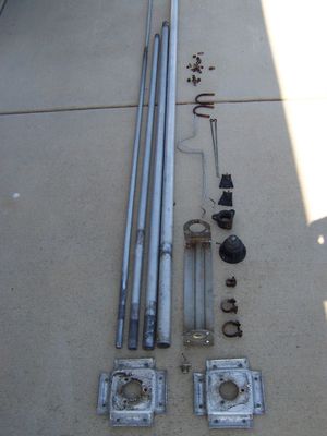
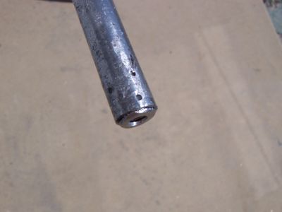
When I was doing the research for the previous Penetrator article, I stumbled across most of the parts for a Penetrator P500 (version 1). There was the vertical radiator with a somewhat straight mounting bracket and most of the matching section, and it was missing the ground radials. As you can see in the first photo, nearly all of it was badly corroded and all the hardware was solid rust. But, the price was right (free!), so I took it home to evaluate just how much of it I could save.
The first task is to completely disassemble the antenna into individual pieces. You have to get down to parts and make an antenna �kit� in order to properly clean and straighten anything requiring it. Sometimes, everything will come apart easily, sometimes it is a struggle.
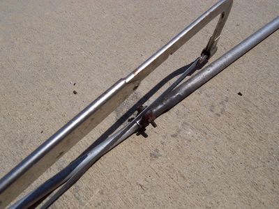
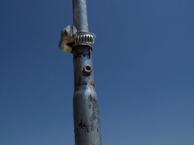
In my case, it was a struggle! Most of the aluminum vertical element pieces were corroded together, and difficult to separate. The second photo shows how to get those rusted clamps apart. By carefully cutting them with a hacksaw (careful not to cut the aluminum), the clamps can be removed easily. Once the clamps are off, you can pull the sections apart. If they won�t separate easily, you can try tapping them with a rubber mallet against a block of wood or use heat from a propane torch. If they are absolutely stuck together, you may have to opt to not separate them for fear of damaging them. We�ll address that later.
In most cases, the plastic parts of the antenna will be cracked or there will be signs of water entry and damage to the base insulator. You need to remove all the plastic parts from the aluminum. Drill out the rivets using the appropriate size drill bit. They come apart much easier than you might think. Rusted bolts are another challenge and sometimes need to be cut off. I was lucky in that most of my rusted bolts were able to be worked apart with lots of oil and work.
The top hat elements were broken and missing on my antenna, and the bolt that holds them to the top section was broken off. This is no big deal, as you will see a bit later.
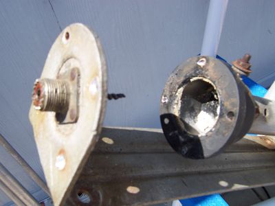
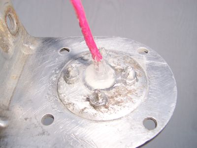
In this photo, you can see why it is important to take these pieces apart! Water made its way inside the base insulator, despite it not being cracked. The corrosion to the aluminum and the connector is obvious! As you can also see, the small wire connecting the coax connector to the thru-bolt is completely corroded away and severed. That explains why this antenna was discarded.
After all the pieces are apart, you need to clean everything and remove all traces of corrosion and rust. I prefer to use mineral spirits and bronze wool or steel wool scouring pads. For the really tough or badly pitted parts, you may want to try some sandpaper.
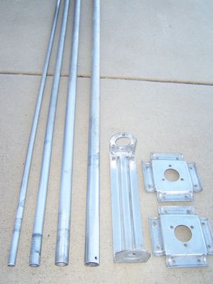
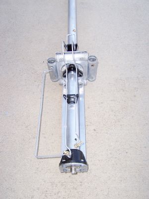
The next photo shows everything apart and cleaned. What a difference! Clean aluminum parts will also ensure good electrical connections later.
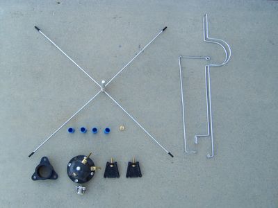
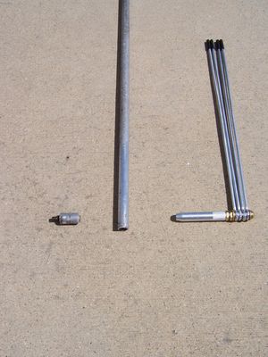
Evaluate all of the non-metal parts of your antenna and see if there are any cracks in them. If they show signs of cracking or becoming brittle, it is suggested that you replace them. The good news for us Penetrator antenna rebuilders is that the plastic parts are still available! Parts are available from Hy-Gain (part numbers at the end of this article) or from an individual supplier named Jim Dent. I contacted Jim for the parts for this Penetrator P500 (contact info at the end of this article). I ordered a complete set of plastic parts and complete top hat assembly and new matching network parts for my antenna. This photo shows the parts I purchased.
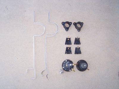
This photo shows the new plastic parts and phasing stub next to my old parts.
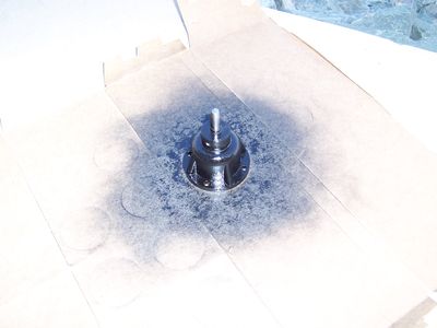
Since I am a big fan of antennas that do not require attention later, I like to coat my plastic parts with a UV resistant paint to prolong the life of them. All my plastic parts got two coats of epoxy paint before getting them ready to install.
Part of the problem with this antenna was water intrusion into the base insulator. In the event water were to find its way in again, I completely coated the new connector and feed wire with silicone. Now, even if water finds its way in, the wire and connector won�t corrode.
When I reinstalled the connector in the bottom of the mounting bracket, I used all stainless steel hardware and coated everything with Penetrox. I also sealed the connector on the inside with silicone for extra insurance.
Getting back to those aluminum tubing sections that don�t want to come apart, even after trying to force them apart, sometimes they are bonded so tightly that you will do more damage than good if you force them apart. Such was the case with my antenna as the top section and the second section were bonded so tight, nothing could break them apart. The key here is to accept the bond and concentrate on assuring you have a good electrical connection. To make sure of that, drill a small hole through both pieces of tubing and thread a sheet metal screw into the hole, using Penetrox to make sure there won�t be corrosion between the dissimilar metals.
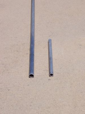
Occasionally, you will run into a situation where the bottom end of a tubing section was bent, and you had to straighten it, but in doing so, the aluminum tubing seems a little weak. That�s an easy repair! Just cut a short piece of tubing the size of the inner diameter of the section you need to stiffen and insert it. Then, use a center punch to make small dents in the outer tubing and hold it in place.
Replacing the top hat threaded insert is simple. First, use a tubing cutter to cut off the top � inch of tubing, which will also take the original threaded insert with it.
Clean the inside of the tubing with sandpaper and apply a bit of Penetrox. Smear a little Penetrox on the new threaded insert and work it into the end of the tubing. You may have to tap it into place using a rubber mallet as it is a tight fit. Use a center punch to dent the tubing the same way you did to add a stiffener as above, to hold it in place.
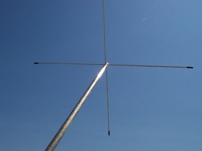
After the insert is in place, make sure it is tight. Apply Penetrox to the threads and assemble the top hat elements into a unit and arrange in an �X� pattern. Thread the top hat assembly into the threaded insert and tighten. It should look like this.
Reassemble the base of the antenna, being sure to sand to a shine and use Penetrox on all connections. Where the base insulator mounts to the mounting bracket, I used some silicone to help seal it and keep moisture out. Use Penetrox on all stainless hardware you use to affix the base insulator.
In my case, I had to make ground radials from scratch. Using 4 different sizes of tubing, I just used the same techniques as used on the vertical to create them. The radials all need to be 105 inches long, according to plans. Drill and insert the ground radials in the radial bracket as shown in the illustrations.
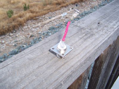
Mount the antenna to your support pole and connect your coax cable. It�s best to start off with the antenna low enough to reach the joint between the lowest and second sections for tuning. I ended up a few inches shorter than the instructions say in order to get mine tuned properly. Of course, you can shorten the antenna much more and get it to the 10 meter amateur band easily.
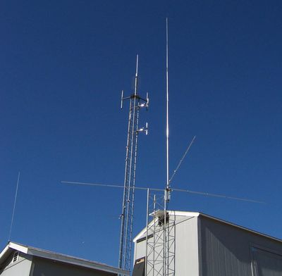
Even from this short test tower, the Penetrator P500 works amazingly well. It is one of the quietest antennas I have here. Comparing it to the wire antennas, it is really the top dog 10m antenna at the QTH now. Signal reports are always very enthusiastic with easy copy on the P500 even when copy is marginal on one of the other antennas. This classic antenna that was destined for the junkyard has a whole new life, and I am proud to have rescued it.
I want to take this opportunity to mention a few tips that might help you enjoy your antenna even more. Some of this applies to other aluminum antennas as well.
First of all, I hear a lot of people say their aluminum antenna SWR changes or goes up when it rains. This is NOT normal. If this happens, it is likely water getting between the vertical and the top ground bracket insulator. Sometimes, it is because this insulator has cracked. On my Penetrator, I sealed the entire area with silicone, including getting silicone between the vertical and the insulator itself. When it rains, my SWR stays exactly where it was when the antenna was dry.
Second, I cannot stress how important it is that all of your connections be very tight. And, I don�t just mean physically tight, I mean low RF resistance. Sand the inside of the upper sections of tubing and sand the outsides of the lower sections of tubing in the vertical radiator and ground planes. Aluminum oxide is an insulator, and it builds up the surface of aluminum very quickly. If aluminum oxide coats the tubing pieces before you assemble them, the RF resistance will be higher than if they were clean. This causes a noisy antenna, and also changes of SWR with moisture and temperature extremes.
Seal your coax! Just because the coax connector is on the bottom of the mounting bracket does not mean it won�t get wet. Water in coax is a real bummer. Use some vapor-block sealant, available from Copper Electronics, and then use 3M brand black tape to tape it up tight. Wrap tape from the bottom�up so that overlaps to not trap water.
Even if you own a Penetrator that is working OK now, it is in your best interest to remove the base insulator and check to make sure you don�t have a big corrosion mess inside it like I did. While you�re at it, you will notice that the original wire size in your base from the coax connector to the thru-bolt is only 18 ga. I suggest replacing this with 14 ga. or larger to improve your power handling capability (if you plan on using legal limit on 10m).
For those of you wanting to rebuild a Penetrator P500 antenna, and want to replace all the rusted hardware with new, I strongly suggest marine grade stainless whenever possible. For your convenience, here�s a shopping list to take to the hardware store with you of every piece of hardware in a Penetrator P500 antenna-
Clamps- (�Ideal� brand)
(10) IDL 6202
(1) IDL 5010
(1) IDL 5016
(3) 1/4" x 1" bolts
(8) 1/4" x 1 1/2" bolts
(12) 1/4" lock washers
(11) 1/4� nuts (preferably nylock type)
(1) 10/24 x 1/2" screw
(5) 10/24 x 5/8" screws
(4) 10/24 x 3/4" screws
(1) 10/24 x 1 1/2" screw
(1) 10/24 x 2 1/2" screw
(3) 10/24 flat washers
(9) 10/24 split washers
(9) 10/24 nuts
(4) #4 x 3/8" screws
(4) #4 flat washers
(4) #4 lock washers
(6) #4 S/S external tooth lock washers
(4) #4 nuts
If you would like to purchase parts directly from MFJ, the company that owns the Hy-Gain name and products now, here are the part numbers you will need:
Top hat radials- Part # 173499
Top Insulator- Part # 463056
Base Insulator- Part # 863427
Base bracket- Part # 160043
U-Bolts- Part # 543792
Insulator rod support(s)- Part # 463642
I would like to thank Jim Dent for an amazing amount of help with this project. Jim can be contacted for any Penetrator P500 part imaginable. What he does not have N.O.S., he will manufacture. Jim can be reached via email- Seagraves26@aol.com
I would also like to thank my gracious friend Gary for the donation of the �junk� antenna for this project. The next time you hear �Wolfie� from N. California on the air, please take a moment to thank him for his contribution.
-Tech 833 |
Starface
Senior Member
Username: Starface
Post Number: 2608
Registered: 1-2005

| | Posted on Sunday, October 18, 2009 - 7:59 am: |
|
Keep it coming Very good Articles.
Again Thanks Paul.
73
George/Starface/KI4NBE
CEF 476 CVC 014 HAM 181
SOUTHEAST CEF NET CONTROL
|
Jimb654
Junior Member
Username: Jimb654
Post Number: 15
Registered: 9-2002
| | Posted on Monday, April 26, 2010 - 5:55 am: |
|
After reading this article I contacted Mr Dent, took my 30+ year old penetrator and headed off to Lexington,Ky and meet with him. I now have a "like new" penetrator. I could not be happier with it. Mr Dent really knows his stuff and really appreciate everything he did for me.
Tech 833 thank you for the great articles on this antenna.
-Jim |
Tech833
Intermediate Member
Username: Tech833
Post Number: 167
Registered: 12-2001
| | Posted on Monday, April 26, 2010 - 11:35 am: |
|
Thank you, Jim.
I shared your post with Mr. Dent. He is really knowledgeable, glad he was able to help you so much.
Your radio 'Mythbuster' since 1998
|
Richiek
Junior Member
Username: Richiek
Post Number: 23
Registered: 4-2008
| | Posted on Friday, March 13, 2015 - 9:01 am: |
|
I am so glad I stumbled onto this post!
Years ago I took down an old antenna for an old widow and took that puppy home to play with.
I never new what kind of antenna it was until now.
It never worked for me so I took it apart and stored it.
Now I know and can hopefully refurb this antenna for future use.
Thanks Tech833! |
|

