| Author |
Message |
    
Forummaster
| | Posted on Wednesday, March 27, 2002 - 12:01 am: | 


|
Make a base radio mic from a PC microphone.
This article will tell you how to use a microphone for a computer for your base station radio. You can use any PC mic with a 1/8" mono plug, including amplified mics and headset boom microphones. NOTE: In order to keep this project simple, you must have a radio that will receive independently of a microphone. In other words your radio will receive without plugging in the mic.
For my experimentation I used my existing PC mic which is Radio Shack's tabletop amplified computer microphone #33-3025, and had excellent results. This mic requires, but does not include, 2 "AAA" batteries for operation.
This is a simple project that requires some minor soldering, drilling, and mic wiring. This is a beginner project, so anyone can enjoy this homebrew invention!
PARTS LIST (All from Radio Shack)
| (1) | Desktop Amplified PC Microphone #33-3025 (2 AAA Batt) | $19.99 | | (1) | 4" X 2" X 1" Plastic Project Box #270-1802 | $2.29 | | (1) | SPST Momentary Push Button Switch #275-609 | $2.79 (2) | | (1) | 1/8" Mono Chassis Mount Phone Jack #274-248A | $1.99 (2) | | (3 feet) | 3-Wire Microphone cable (or similar) #8403-60-U1000 | $2.64 | | (1) | Microphone Plug | $1.99 | | TOTAL PARTS COST | $31.69 |
TOOLS
Soldering Iron
Solder
Ohmmeter
Phillips Screw Driver
Short section of Jumper Wire (3")
Utility Knife
Drill (cordless or electric)
1/2" Drill Bit
1/4" Drill Bit
Start by figuring out the wiring configuration to your radio's microphone. You will need to know which pin is for Transmit, Modulation, and Ground. These are the only pins you will need to worry about, as this project works only on radios that receive independently of having the microphone plugged in.
Building the project is simple once you've figured out which pin controls what on your radio's microphone connector. Start by measuring out three feet of microphone cable, or any other similar cable that contains three conductors. One end of the cable, remove about one inch of the outer insulation exposing the three wires. This is the end you will be using to connect the mic plug to connect to your radio. On the other end remove about three inches of the outer jacket exposing the three wires inside. This end will be used to make the connections inside the project box. Remove about 1/8" of the insulation of all three wires on each end of the cable so you can attach them to where they belong. At this time pick which of the three wires will be going to what on the radio's mic jack. Hopefully you have mic cable with three different color wires. One wire needs to go to TRANSMIT, one to MODULATION, and one to the GROUND pin on your radio's mic jack. At last, plug in your soldering iron so it will be ready to go when it's time to solder.
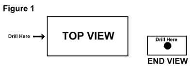
Next, drill a 1/4" hole in one end of the project box about midway between the bottom (with the indentations for the feet) and the top (where the cover attaches), as shown in Figure 1. This will be the hole that the mic cable runs through.
Secondly, drill another hole, 1/2" in diameter in the top cover of the project box for the switch. It is important to use the PLASTIC cover that comes with the project box, because the recessed fashion in which the metal cover sits in the box will NOT allow enough room once the switch is installed. Drill this hole about 1/3 of the way from the end of the cover on the same end that the microphone cable will run through. Don't put it too close to the edge of the cover or it will interfere with the microphone cable. See Figure 2

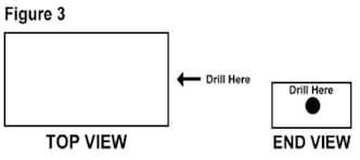
The third and final hole you need to drill is of 1/4" in diameter and in the same location of the mic cable hole but on the opposite end. See Figure 3. This hole will be for the 1/8" phone jack where the PC microphone plugs into. All the drilling you have to do, is now complete with this third and final hole.
Feed the microphone cable into the project box through the whole you drilled in the one end. Be sure to feed through the end of the cable with the three inches of jacket removed and tie a knot in the cable on the inside of the box below the exposed wires. This will be for strain relief, and your cable wont pull out of the project box.
Next, attach the SPST momentary on Push-Button switch in the hole you have already drilled in the cover of the project box, and fasten on the inside with the supplied washer and nut.
Finally attach the 1/8" phone jack in the other 1/4" hole in the end of the project box, and fasten it on the outside of the box with the supplied nut and washer.
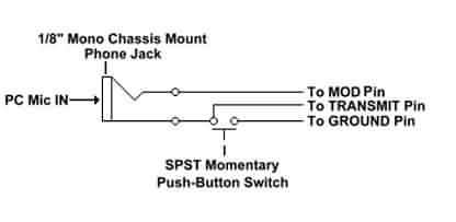
Now, using your ohmmeter, check for continuity on the phone jack to find the soldering lugs that coincide with the center connector and the ground. The main hole is ground and the pin that snaps against the side of the 1/8" stereo jack is center. Once you know which is which, make note of it, as we will use this later.
Now, with your soldering iron, tin the two legs of the switch and the two lugs on the phone jack you are going to solder to.
Then tin the ends of the three wires of the microphone cable. Next, strip 1/8" of insulation from both ends of a piece of jumper wire and tin both.
Now you are ready to solder all of the connections together. Solder the end of the wire inside the microphone cable going to the MODULATION pin on your radio's mic jack to the center lug on the phone jack.
Solder one end of the jumper wire to the ground lug on the phone jack.
Then solder the wire inside the microphone cable going to the TRANSMIT pin on the radio's mic jack, and the jumper from the phone jack to one leg of the switch. You may have to twist the two wires together to make it easier to solder both of them to the same leg of the switch at the same time.
Next, solder the wire inside the microphone cable going to the GROUND pin on your radio's mic jack to other leg of the switch.
When the solder connections are complete and the circuit is wired in accordance with the schematic below, fasten the cover onto the project box using the supplied screws.
All you need to do now is to wire the microphone plug on the other end of the microphone cable so it will work with your radio. It is the assumption of the author that you already know how to do this so I won't explain it here. Plug the microphone from your computer into the phone jack on one end of the box, plug the mic into your radio, and press the button to key the radio and talk. Enjoy!
|
|