| Author |
Message |
    
Admin
| | Posted on Monday, November 12, 2001 - 9:53 pm: | 


|
Step 2
Voyage 9000 Modification
NPC-RC Modification:
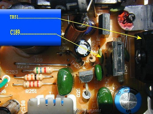
Position the radio with the knobs facing you , and with the component side up.
You will start by looking near the rear of the PCB on the right hand side. Locate a large black transistor, mounted to the side of the case labeled TR-51. It has the markings of 2SB754. We are looking for a part (capacitor) just in front of TR-51 labeled C189.
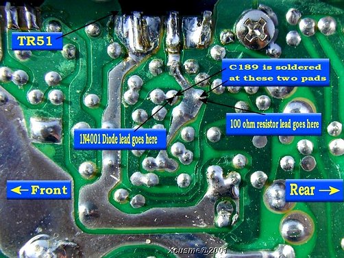
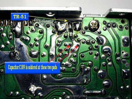
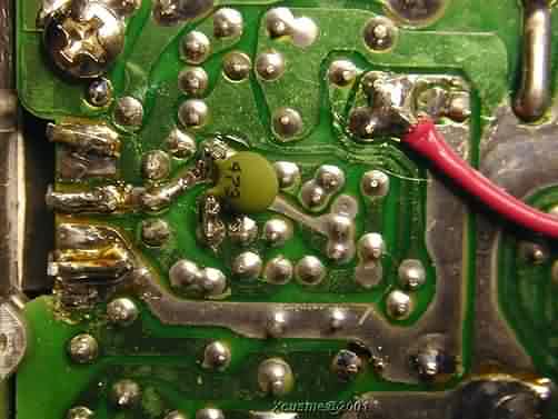
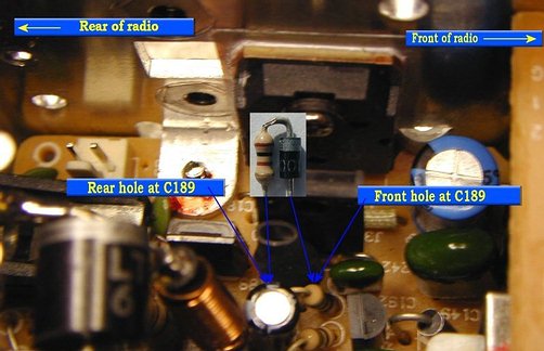
The next two pictures are for reference, showing the points explained in the next few steps. Refer to these pictures for part locations on the solder side of the PCB.
Unsolder capacitor C189 and keep this part handy, we will be re-installing it later.
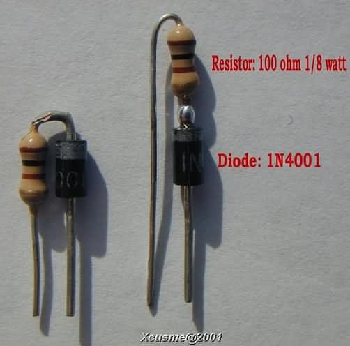
From our additional parts, find the 1N4001 diode and the 100-ohm resistor.
Clip the wire lead from the banded end of the 1N4001 diode so that about 1/8 to 3/16 of an inch sticks out past the end of the diode
Clip the wire lead from one end of the 100 ohm resistor (either end) so that about 1/8 to 3/16 of an inch sticks out past the end of the resistor
Position both parts END to END with the 1/8 stubs lying side by side and solder them together.
Bend the remaining resistor wire lead over into a hairpin shape
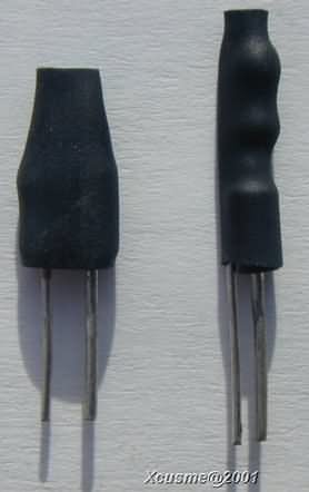
You can, if you prefer, cut the wire leads a little longer, bend the leads at right angles and place the diode and the resistor side by side, then solder them together. Electrically speaking, both options are the same. Here is a picture showing both options. Pick one or the other.
Cover the diode-resistor with a short piece of heat shrink tubing and apply heat to shrink tubing
Note: The diode wire lead will be LARGER in diameter, the resistor wire lead will be SMALLER in diameter of the two wires protruding from the heat shrink tubing. Again, yours should look like one the two shown.
With radio knobs facing you, component side up.
Insert the diode-resistor into the holes where you removed the capacitor at location C189.
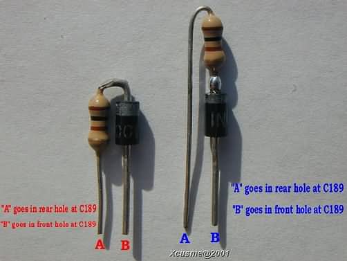
Be sure you place the diode wire lead (LARGER of the two) into the hole closest to the FRONT of the radio. The SMALLER resistor wire lead will go into the hole closest to the REAR of the radio. The next picture shows the diode-resistor without heatshrink tubing for reference only. Your diode-resistor will have the heatshrink tubing installed.
Flip the radio over to the solder side and solder the diode-resistor to the PCB. Clip off the extra wire leads protruding from the PCB.
Re-install the capacitor, C189 across the same two points where it was originally soldered to...(they are the same pads you just finished soldering the diode-resistor to) Try to place the capacitor flat against the PCB so as not to obstruct the top cover. Trim the leads of the capacitor as needed before you solder it across the pads. Use the small pair of needle nose pliers to hold the part in place while you solder it to the PCB. This puts capacitor C189 back into the circuit, it's just on the underside of the radio.
This picture shows what the diode-resistor looks like installed on the component side of the PCB. As you can see, I used the "Side by Side" option for the diode-resistor . It's a little less conspicuous because if it's low profile.
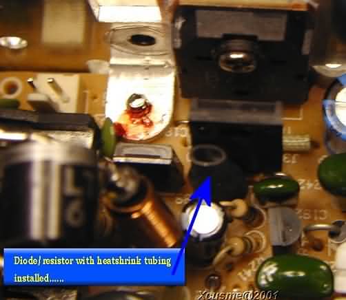
This picture shows basically the same thing, except it shows how the diode-resistor relate to the other parts.
Next , we will disable the on board AMC circuit |
|