| Author |
Message |
    
Admin
| | Posted on Tuesday, November 13, 2001 - 12:18 am: | 


|
Step 4
Voyage 9000 Modification
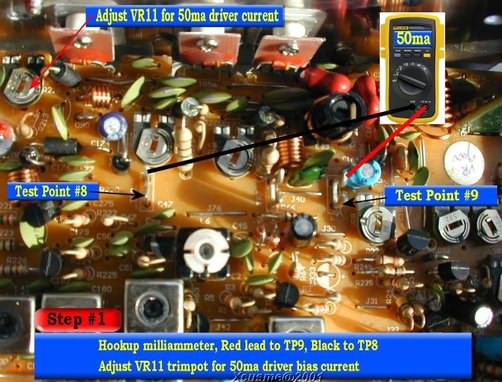
Adjusting the Driver bias:
WARNING: DO NOT adjust this trim pot without hooking up a meter. This is not guess work! Too much bias current WILL damage the driver output transistor. Also, too much bias current can cause the SSB to warble.
Connect a Dummy Load to the radio antenna connector
Connect the Microphone to the radio
Connect radio to 13.8VDC power supply with fused power leads,
DO NOT turn radio ON at this time
Position the radio, knobs facing you, component side up.
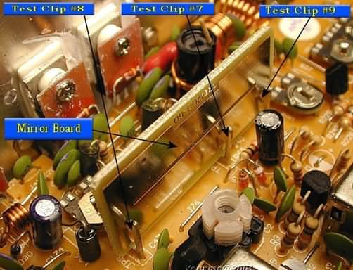
Look towards the rear of the radio on the left side and find the "Mirror board" ...some call it the "Silver board"
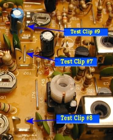
You will notice that the Mirror Board is sitting in 3 clips labled TP8, TP7, TP9 reading from left to right. I use the term "Test Clip", they are also "Test Points (TP)", hence the markings on the PCB of TP8, TP7, TP9.
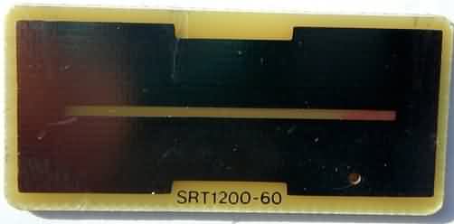
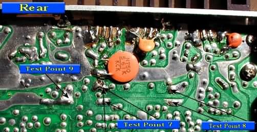
The next picture is for reference . This shows the solder side of the PCB , and the locations of the Test Clips.
Remove the Mirror board, by lifting it straight up. Put the Mirror board aside, we will install it again later. This picture shows the Mirror board removed .
Connect the DVM -ammeter test leads to the following test points, set meter to the 200-milliamp scale
Connect the DVM-Red meter lead to TP9
Connect the DVM-Black meter lead to TP8
Turn the radio ON
Adjust the radio controls to SSB LSB or USB mode, No Modulation
Depress the microphone key
Using a PLASTIC (or other non-metallic) tuning tool
Adjust VR11 for 50ma reading
Turn the radio OFF
Using a pen, mark the position of the center wiper arm on the edge of the trim pot (VR11) to mark your setting.
Once this adjustment is made.... Do not change it.
This completes the driver bias adjustment.
Continue to next section: Adjust Final Output Transistors Bias currents |
|