| Author |
Message |
    
Admin
| | Posted on Tuesday, November 13, 2001 - 1:28 am: | 


|
Step 5
Voyage 9000 Modification
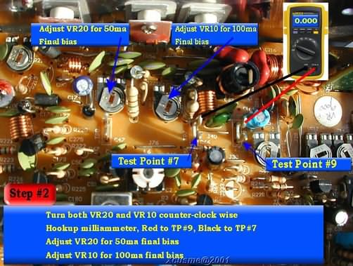
Adjust Final Transistor(s) Bias Current:
WARNING: DO NOT adjust either of these two trim pots without hooking up a meter. This is not guessing work! Too much bias current WILL damage the final output transistors.
Use the same radio and DVM-meter setup as from previous step:
Adjust VR20 and VR10 fully counterclock wise, this sets both trimpots to zero current
Move the DVM-meter Black lead from TP8 to TP7. Leave the Red meter lead connected to TP9
Turn the radio ON
Depress the microphone key
Using PLASTIC (or other non-metallic) tuning tool
Adjust VR20 for 50ma reading
Adjust VR10 for a total reading of 100ma
These last two steps apply 50ma bias current to each of the finals. The final reading of 100ma is the TOTAL bias current for BOTH of the finals, (50ma for VR20 + 50ma for VR10 = 100ma TOTAL)
Turn the radio OFF
Disconnect the DVM-Meter from TP7 and TP9
Using a pen, mark the position of the center wiper arms on the edges of the trim pots (VR20, VR10) to mark your setting.
Once these adjustments are made.... Do not change them.
This completes the final output transistors bias adjustment.
Disconnect the radio power supply cable
Remove the Dummy load
Disconnect the microphone cable
Next we will Volt the Final Output Transistors |
|