| Author |
Message |
    
Admin
| | Posted on Tuesday, November 13, 2001 - 1:45 am: | 


|
Step 6
Voyage 9000 Modification
Volting the Final Output Transistors:
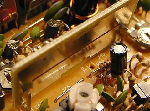
Please study the next picture and use it for reference for the following steps.
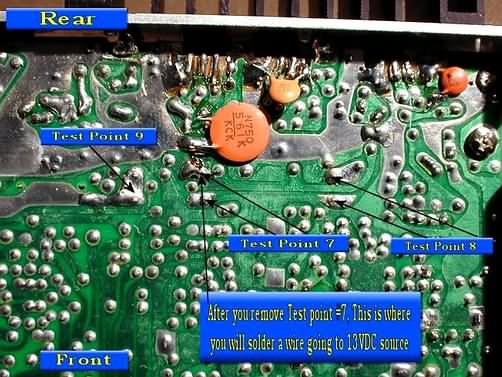
Position the radio, knobs facing you, component side up.
Look towards the rear of the radio, on the left side and locate 3 Test Clips labled TP8, TP7, TP9 reading from left to right. I use the term "Test Clip", they are also "Test Points (TP)", hence the markings on the PCB of TP8, TP7, TP9.
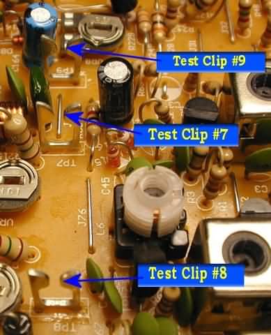
Locate the Test Clip at TP7
Flip radio over to the solder side and unsolder Test Clip7 from the PCB and remove it, you won't be needing this Test Clip again.
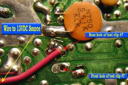
Since we are still working on the solder side of the PCB, lets install a jumper wire from a 13.8VDC source to the REAR hole of where the Test Clip at TP7 was just removed.
Strip about 1/8 to 3/16 of an inch of the insulation from the end of the 1-foot piece of 18ga. Stranded wire.
Pre-tin the end of this wire with solder (heat the end of the wire and apply a small even coat of solder)
Solder this pre-tinned end of the wire to the REAR hole of where Test Clip 7 at TP7 was ORIGINALLY installed. Anywhere on that same solder pad will do. Try to keep the wire reasonably flat against the PCB while you solder it to the pad. Add more solder as needed to effect a solid shiny connection.
Leave the FRONT hole of the old TP7 Test Clip vacant.
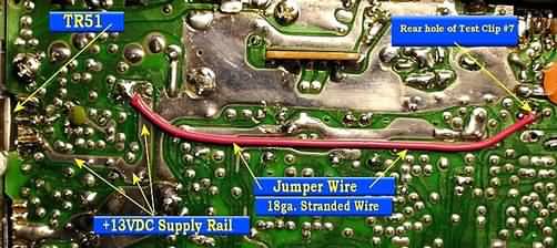
Lay the jumper wire neatly across the PCB, towards the left, and measure enough wire to make a connection shown in the next picture. This connection is to the 13.8VDC supply rail. This "Question Mark" shaped PCB circuit trace IS the 13.8VDC source. A connection anywhere on this circuit trace will do. I soldered the jumper to the place indicated because there were other parts already soldered there and it's rather easy to just reflow the solder at that junction for a solid connection. That's why we pre-tinned the end of the wire. Add more solder as needed to effect a solid shiny connection.
So, to re-cap:
Cut wire to length
Strip about 1/8 to 3/16 of an inch of the insulation from the end
Pre-tin the end of this wire with solder (heat the end of the wire and apply a small even coat of solder)
Solder the wire end to the location shown.
Flip radio back to the component side
Re-Install the Mirror board to it's original position in Test Clips TP8 and TP9. This completes the Volting of the Final Output Transistors.
In the next step, you will adjust the RF power levels for both the HIGH and LOW front radio control knob settings. |
|