| Author |
Message |
    
Admin
| | Posted on Tuesday, November 13, 2001 - 2:23 am: | 


|
Step 7
Voyage 9000 Modification
Set High and Low RF Power Levels:
Position the radio, knobs facing you, component side up.
Connect a coax jumper between the radio antenna connector and the SWR-Power Meter input-radio connector
Set the SWR-Power Meter to read RF watts on 20-Watt Scale
Connect a Dummy Load to SWR-Power Meter antenna connector
Connect the Microphone
Locate VR13 (Located near Center-Rear) this trimpot will adjust the AM RF High Power setting
Locate VR16 (Located near Center-Rear) this trimpot will adjust the AM RF Low Power setting
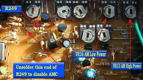
Turn VR13 fully counterclock-wise. NOTE: Failure to do this step will result in a very high RF output during the next steps!
Connect radio to 13.8VDC power supply with fused power leads
Turn the radio ON
Adjust the radio controls to AM mode, channel 20
Adjust the radio front RF output control knob to HIGH setting (fully clockwise to the right)
Key the Microphone (no modulation)
Adjust VR13 for a reading of approximately 5 to 7-Watts
UnKey the microphone
Switch the SWR-Power Meter to low range (10 to 20 watts)
Key the Microphone (no modulation)
Adjust VR13 for 7- Watts again to finalize High RF Power setting
UnKey the microphone
Adjust the radio front RF output control knob to LOW setting (fully counterclockwise to the left)
Key the Microphone (no modulation)
Adjust VR16 for a reading of approximately 1.5 to 2.0- Watts
Turn the radio OFF
This completes the RF Power Output Adjustments
You have now completed the NPC-RC modification to your Voyage 9000 Export radio.
Disconnect all power and antenna connections.
Feel free to replace the covers in the reverse order in which they were removed. Remember to reconnect the speaker connector to the PCB when you replace the bottom cover. |
|