| Author |
Message |
    
Admin
| | Posted on Friday, December 28, 2001 - 11:44 am: | 


|
The Antron 99 EXPOSED!
by Tech 833
Have you ever wondered what was inside the Antron 99 antenna?
A long time ago, I purchased a Solarcon Antron 99 antenna for my propagation beacon. The Antron 99 is really a CB antenna, but with only slight retuning, it works very well on the 10 meter band. In the Antron advertising, it explains that it is a '1/2 wave over 1/4 wave variable mutual transductance tuned antenna' with a dB gain of 9.9 dBi. No way I thought.... However, the price was low, so I bought it anyway. After discovering that the Antron 99 performed worse than the 5/8 wave ground plane it replaced, I set out to discover why. What follows is my findings after dissecting 2 separate Antron 99 antennas.
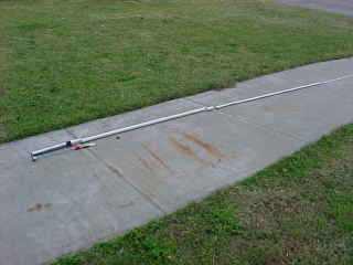 | In this photo, you can see the insides of the Antron 99 laid alongside the shell it was once housed in for size reference. In this photo, you see what is inside the base and how it fits inside the base section. Except for the lower 2 feet of the Antron 99, all the rest of the antenna contains nothing more than a straight piece of #16 bare copper wire! |
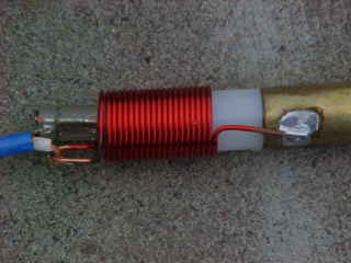
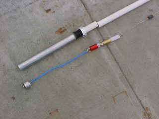 | Here, you can clearly see the small section of coaxial cable which connects to SO-239 connector in the bottom of the mounting pipe and to the coils of the matching section. No 'magic' here at all. Just above the coils is the capacitor coupling which is made of a nylon spacer and brass tubing. The 'twin ring' match merely changes the inductance of the outer tuning coil. |
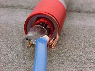
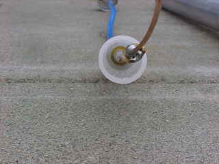 | In this photo, you can look down inside the capacitor coupling unit. This photo was taken from the radiator end looking back toward the base assembly. To get an idea of how this works, imagine plates of a battery. Current can flow between them, right? The only difference is that instead of battery acid or gel electrolyte, the nylon spacer assembly is the electrolytic for in this case, 'plates' of the capacitor. The wire going down the middle does NOT go all the way through (see the schematic at the bottom of the page). Notice the HORRIBLE soldering job! Obviously, there was not enough heat applied to this solder joint. Also, by adding this much series capacitive reactance, there must be a lot of series inductance to offset it. A very lossy approach! |
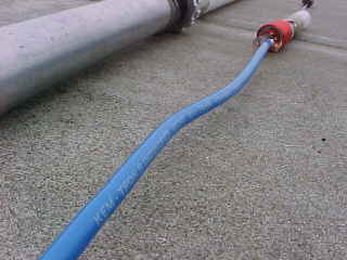 | This photo gives you a good view of the coax type and also how the inner impedance matching coil fits inside the outer tuning coil. Since the Antron 99 is nothing more than a standard end fed 1/2 wave dipole, the base impedance is nearly 1,000 ohms. In order to get a 50 ohm feedpoint on a 1/2 wave element, the antenna is shunt fed. The inner coil provides the 50 ohm point at the base of the radiator. The outer tuning coils adjusts the reactance over the selected bandwidth. Once the reactance is at or near zero, the SWR will be very low. |
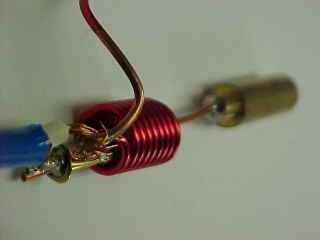
 | This photo provides a closer look at the matching section coils. If you look carefully, you will be able to see where the inner and outer conductors of the coaxial cable connect. If you look even CLOSER, you will see that the coaxial cable's center conductor is not even soldered to the end of the outer tuning coil! The copper strands are merely wrapped around the bare copper end of the tuning coil! This may explain why this antenna was so unstable in windy conditions when the tower would vibrate. This also shows where the outer tuning coil solders onto the outside of the brass tube which provides one plate of the 2 coupling capacitors. |
 | In this photo, you can more clearly see the coils inside one another and also the unsoldered connection from the coaxial cable center conductor to the outer tuning coil end. The clear plastic that the coaxial outer shield runs through is only a spacer to keep the conductors from shorting to one another. It has no tuning or electrical purpose. If you look closely, you can see that the solder connection inside the plastic shell is just a 'blob job' as well. |
 | This photo shows the inside of the capacitor coupling unit. The brass cylinder on the end of the wire form the inner conductor or 'plate' of the coupling capacitor. There is an identical brass cylinder on the end of the long copper wire which forms the antenna element. The two cylinders fit inside the brass sleeve seen in the photos above, but they do not touch each other end to end. There is a small space left which would act like a spark gap in the case of lightning strike. Notice here, the solder job on the capacitor components was superb. For a more detailed idea of how this works, check out the schematic diagram below. |
So what is the TRUE gain of the Antron 99? Assuming a 1/2 wave shunt fed dipole in free space, minus the losses associated with the series capacitance and inductance, according to my math, the Antron 99 has 1.8 dBi gain. That is to say, the Antron 99 has 1.8 dB gain on the horizon over an isotropic radiator. Referenced to a center fed 1/2 wave dipole, which is the industry standard, the Antron 99 has a NEGATIVE gain of 0.3 dB. This could also be stated as -0.3 dBd. As a reference, my old 5/8 wave ground plane antenna had 3 dBi gain. So, the Antron 99 was a step 'down' so to speak. Replacing the Antron 99 with a new 5/8 wave ground plane antenna will result in a 1.2 dB gain improvement.
So, you ask... Why would I buy a $50 antenna only to cut it up? Because I knew for a fact that the marketing hype was horribly overstated. Even IF you were to design a true 1/2 wave over 1/4 wave stacked dipole antenna, you would not get 9.9 dBi gain on the horizon. But just in case there really was some 'voodoo' happening inside the Antron 99, I had to see what it was. As you can see, the Antron 99 has no voodoo at all. The Antron 99 is just a 1/2 wave end fed dipole with extra capacitive coupling to isolate the antenna base from high voltages in case the installer happens to drop it across power lines and the radiator happens to make contact with high voltage.
CLOSING STATEMENTS: The Antron 99 will NOT outperform any of the other typical 5/8 or 1/2 wave antennas like the popular 'Ringo'. However, for a modestly priced fiberglass antenna that is less visually intrusive than the 'ground plane' style antennas, it will certainly meet those needs |
|

