| Author |
Message |
    
Missie
Junior Member
Username: Missie
Post Number: 32
Registered: 10-2006
| | Posted on Sunday, January 20, 2008 - 8:48 pm: | 


|
I pluged in my 148 backwards now lights come on but no transmit or receive is there a diod like in the 29's or did I do something more.
thanks |
Patzerozero
Senior Member
Username: Patzerozero
Post Number: 4119
Registered: 7-2004
| | Posted on Sunday, January 20, 2008 - 9:30 pm: |
|
like the 29, take cover off, look inside back of radio where 12vdc cord plugs in. HOPEFULLY, you see a burn mark on the inside of the plug's positive side where a 1n4003 diode used to be. replace the diode. some radios it goes directly across positive & negative terminal, on others it goes from positive to circuit board ground. |
Missie
Junior Member
Username: Missie
Post Number: 33
Registered: 10-2006
| | Posted on Tuesday, January 22, 2008 - 8:50 pm: |
|
I looked at that and they are all there! I have 12 volts through the one that goes from pos to neg the 2 that go from neg to chaise ground I get nothing through them. the lights come on the channel led lights and when you key the mic the red light comes on but no trans or receive it acts like the final is out but I have never blowen one when I've hooked one up backwards . any other ideas thank.. |
The_horseman
Junior Member
Username: The_horseman
Post Number: 16
Registered: 11-2007
| | Posted on Wednesday, January 23, 2008 - 10:07 am: |
|
If you figure this out, please let me know. My 148 has done this for months. I get it to come on by jumping a chip diode on the bottom side of the board. It works fine until I take power away.
CEF # 949
CEF Ham # 272
|
Lester_elm
Junior Member
Username: Lester_elm
Post Number: 22
Registered: 12-2007

| | Posted on Wednesday, January 23, 2008 - 10:27 am: |
|
Bruce, is Tx/Rx dead in all modes (AM and SSB)? I would suspect IC4 (MB3756) Regulator IC. This IC provides the B+ voltage to Tx, Rx, and PLL. I have sent you an email with the correct voltages for this IC. Hope this helps.
CEF #964
HAM #276
Ham Radio - Talk worldwide on a tin can and a wet noodle
|
Tech237
Moderator
Username: Tech237
Post Number: 945
Registered: 4-2004
| | Posted on Wednesday, January 23, 2008 - 3:26 pm: |
|
Check the final as I think that has 12v applied when ever voltage is applied to the radio even if the radio is switched off.
Having said that Lester is probably more accurate.
Simon
Tech237
N7AUS
|
Lester_elm
Junior Member
Username: Lester_elm
Post Number: 25
Registered: 12-2007
| | Posted on Thursday, January 24, 2008 - 10:50 am: |
|
To prevent this from occurring in the future a simple full-wave rectifier added to your radio(s) will allow you to connect power without regard to polarity.
Here is the schematic: 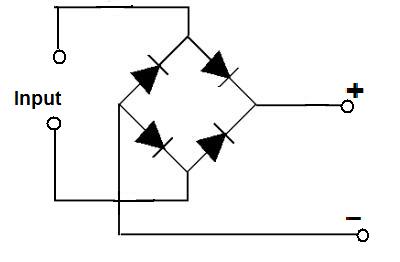
The rectifier looks like this: 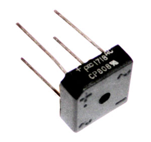
Mount the rectifier inside the radio.
Remove the power wire connections from the circuit board and connect the output of the rectifier (observing polarity) to the board.
Connect power wires to the 'Input' terminals.
Now, regardless of how you connect the power wires to your battery/power supply, the radio will still operate properly without fear of 'blowing it up'.
CEF #964
HAM #276
Ham Radio - Talk worldwide on a tin can and a wet noodle
|
The_horseman
Junior Member
Username: The_horseman
Post Number: 17
Registered: 11-2007
| | Posted on Thursday, January 24, 2008 - 11:03 pm: |
|
On the solder side of the board, approximately 1 1.2 inches back from the front, close to the center of the board, their is a black chip (diode). with power applied to the radio, and switched on, jump both sides of the chip, approximately 1 second. If it is the same problem as my unit, your tx/rx will come back to normal, until you remove power from the unit. The problem is not contibuted to that diode, but something else in the radio.
Still have not figured it out on mine, but the jumper trick gets the unit to life and usable.
Also, I have replace the MB3756, was not the problem.
CEF # 949
CEF Ham # 272
|
Lester_elm
Junior Member
Username: Lester_elm
Post Number: 25
Registered: 12-2007
| | Posted on Friday, January 25, 2008 - 8:03 am: |
|
Louis, what does this 'diode' connect to? Tell me what component it is connected to so I can find it on the schematic and I will try to find the solution to your problem. I need the component ID that it connects to (ie. TR20, C110, R150, etc). I do not have a 148GTL radio but I do have the operators manual, schematics and service manual.
CEF #964
HAM #276
Ham Radio - Talk worldwide on a tin can and a wet noodle
|
Tech237
Moderator
Username: Tech237
Post Number: 947
Registered: 4-2004
| | Posted on Friday, January 25, 2008 - 9:44 am: |
|
DOnt use the bridge systrem unless you supply pushes more than 13V. The reason being the diode bridge will drop around 1.2V and could cause other components to be under-supplied by voltage.
1.2V may not sound like much, but in many radios most circuits are running close to their lower voltage limit to start with.
If you radio doesnot already have one just connect any common recitfier diode across the power input so that the cathode connects to the positve side and the anode to the negatove side. In normal usage this diode will by biased off and have no effect. reverse connect power, the diode will conduct, place a short across the power terminals and simply blow the fuse. Simple, safe and no effect on the rest of the radios - all the reason that manufacturers generally use that method.
Simon
Tech237
N7AUS
|
Lester_elm
Junior Member
Username: Lester_elm
Post Number: 27
Registered: 12-2007
| | Posted on Friday, January 25, 2008 - 11:32 am: |
|
Thanks for the clarification, Simon.
The rectifier method does need 13+ volts to be effective. I assumed that most, if not all, operators used a standard 13.8 volt supply.
The diode across the power input does work most of the time, but not always, as Bruce found out. The protection diode in the radio sometimes opens instead of shorting out. When this happens, the protection is bypassed and you introduce reverse current flow into the rig, which can wreak havoc.
Even though the rectifier bridge has a voltage drop of ~1.2V it can be used successfully on a system that has a 13.8V supply.
Personally, I have adjusted my power supplies to 14.5v and use the bridge in my power distribution strip.
It is a little extra work, but is well worth it when it saves an expensive radio from being fried and having the peace-of-mind of knowing, that if/when you do accidentally wire the radio up backwards, it is protected.
CEF #964
HAM #276
Ham Radio - Talk worldwide on a tin can and a wet noodle
|
The_horseman
Junior Member
Username: The_horseman
Post Number: 18
Registered: 11-2007
| | Posted on Friday, January 25, 2008 - 3:24 pm: |
|
The diode that I jump to get it going is D35, on the solder side of the board. There is another similar diode, close to the same area that will also jump start this radio.
D35 ties into the 11.325 xtal on one leg and r149 and c2321 on the other.
As stated earlier, this diode is not the problem, but a means to jump start the radio. I am sure my issue is much the same as the one that Missie has, it was reverse polarized on hook-up in another truck, popping the fuse in the process. There is not diode on the positive coming into the radio. When I have time, I play with it, but other projects have taken precedence over this one.
This radio has been converted to 10 meters, so it is not longer used as a CB (11 meter) rig. Would like to know why it does this though.
Thanks
CEF # 949
CEF Ham # 272
|
Twowatt
Member
Username: Twowatt
Post Number: 79
Registered: 7-2005
| | Posted on Saturday, August 23, 2008 - 10:46 am: |
|
well, you could always put a 6/22 diode (forward biased) in place of the Positive wire jumper on the back of the DC connector that goes to the circuit board. If 13.8V is connected correctly, then the radio will operate at approx 13.1V -- if connected backwards, the radio won't turn on.
(Use the 6/22 on high power/dual final radios -- use a 6A05 diode on single 1969/2312 final radios -- and you can use a MR5401 on non-peaked radios)
regards |

