| Author |
Message |
    
Jameslarson
Intermediate Member
Username: Jameslarson
Post Number: 291
Registered: 4-2006

| | Posted on Wednesday, April 04, 2007 - 2:35 pm: | 


|
Hello. I have a van, so thus, I have good height, and lots of surface area. I would love to go crazy and put 3 or 4 predator 10K antennas up. I'm sure it would be very directional. Few questions.
1. What would the distnace between each antenna have to be?
2. I know that there is coax for co-phasing 2 antennas. But how do you cophase 3 or 4 antennas?
3. Would the cable still be 75 OHM just like regular 2 antenna co-phasing?
4. And, do they make this special cable that can handle over 1KW?
Help me out anyway you can. Drawings, etc.. Be as specific as possible. I am serious about doing this. Thanks. |
Goat373
Intermediate Member
Username: Goat373
Post Number: 339
Registered: 3-2005

| | Posted on Wednesday, April 04, 2007 - 7:53 pm: |
|
it is my understanding that you would only have to feed one of the antennas...its just like a beam. Well...half of one.
I dont know the exact spacing off the top of my head, but i think you would be limited to two antenna on the top of your van....
Feed the rear one and ground the front one.
The front(director) should also be 5% shorter i think, remember all my figures right now are off the cuff, im at work with no literiture
Brian
CEF574
KI4LXH
"The more you learn...the more you realize how little you know"
|
Kid_vicious
Senior Member
Username: Kid_vicious
Post Number: 2471
Registered: 9-2004
| | Posted on Wednesday, April 04, 2007 - 9:32 pm: |
|
goat is right,
do it like a beam, not co-phased.
i have an old CB projects book that shows how to make a 4 element mobile antenna.
only have coax feed to the driven element, the rest are parasitics. think of the van as the boom.
here is a link to the thread where we discussed this:
http://www.copperelectronics.com/cgi-bin/discus4/show.cgi?tpc=34&post=150429#POST150429
have fun, i hope you try this!
matt
anyone wanting a "clean signal", just look to the left and build one of these!!!
|
Jameslarson
Intermediate Member
Username: Jameslarson
Post Number: 292
Registered: 4-2006
| | Posted on Thursday, April 05, 2007 - 9:50 am: |
|
OK, you say ground the front one. Do you actually mean to ground the antenna itself (In other words the center conductor of the mount)? Or do you mean just ground the part where the shield would normally go? |
Jameslarson
Intermediate Member
Username: Jameslarson
Post Number: 293
Registered: 4-2006
| | Posted on Thursday, April 05, 2007 - 12:58 pm: |
|
Hey Kid V. I checked that link you had. Thanks.
How far apart must each antenna be?
I'd like to have as many antennas up there as possible. I know I would need one reflector in the back, the driven element in the middle, and then as many directors as possible after that, although it looks like after having 4 directors, the DB gain starts to not get that much better. So in all, I guess I would like to have 6 antennas up there (4 directors, 1 driven, 1 reflector).
How far apart on each?
How tall (short) each antenna?
I am assuming that each director gets shorter and shorter as it gets further from the driven element correct?
I really plan on doing this. Thanks. |
Romstar
Member
Username: Romstar
Post Number: 70
Registered: 3-2007

| | Posted on Thursday, April 05, 2007 - 2:39 pm: |
|
I knew a fella that did something similar to what you are talking about. He mounted what looked like a roof rack on top of his truck, and there was an antenna on each corner.
He could drive two front, two rear, or two on either side, or select any corner and make it super directional.
It was an amazing set up, but I never saw how he built it, or really asked him about the particulars.
I did see it in action, and I can tell you that it DID work, and it worked amazingly well. Looked some funny, but man did it talk.
I think he's still around here somewhere, so if I run into him I will ask him about his mobile array.
Now that I am thinking back on it, it sounds a bit like a four element mobile super scanner. I know he had some sort of switching rig in the truck that controlled the antennas, so maybe there is something there to think about.
If I get any information, I will pass it on.
Romstar |
Kid_vicious
Senior Member
Username: Kid_vicious
Post Number: 2474
Registered: 9-2004
| | Posted on Thursday, April 05, 2007 - 11:28 pm: |
|
james,
this is all the info i have:
the pic in the book is a VW bug, facing towards the left.
it looks like the idea is to have the tops of all the antennas at the same height.
this is why the antennas at the front and back of the vehicle are mounted to the bumper.
in the pic i have, from front bumper antenna to the next one back is 42". from that one to the driven element is 42", and the driven element to the reflector is 38".
i dont think its the actual distances that matter, its the relationship between them.
yes, the center pins on all antennas except the driven element are grounded.
think of the van as the boom.
they must all be inline with eachother.
best of luck, i want to try this someday.
matt
anyone wanting a "clean signal", just look to the left and build one of these!!!
|
Jameslarson
Intermediate Member
Username: Jameslarson
Post Number: 294
Registered: 4-2006
| | Posted on Friday, April 06, 2007 - 8:13 am: |
|
Sorry for all the questions, but the directors are grounded center pin as well??????? As well as the reflectors??? |
Vanillagorilla
Advanced Member
Username: Vanillagorilla
Post Number: 978
Registered: 4-2005

| | Posted on Friday, April 06, 2007 - 9:55 am: |
|
Yes James...think of your "directors" as magnets drawing your signal towards them....parasitic elements. Whichever side of the transmitting antenna you position them is the direction of your radiated signal and they must be in line. A whole bunch of work just to throw your signal in ONE direction in relationship to your van....to talk to someone behind you you's have to drive backwards 
If you REALLY want to try this at least put your directors on fold over mounts to lay them down when your mobile and want true omnidirectional radiation. Pull up to the beach pointed S/W and stand up the radials to work DX 
How about this...stay with me here...Buy the Maco 3 element beam and hard mount it on your roof with the mast and TV antenna rotor inside the van. You have about 5.5ft inside the van for a mast you could raise when you park. Mount the 10k you already have on a gumball mount above the beam. An antenna switch inside the van would switch between omni or uni-directional antenna.
Would be a H3LL of a sight to behold I tell you that!
Of course I'm kidding here but I can tell the wheels in your head are turning. I'm game for the project...as before...you buy the beer and pizza 
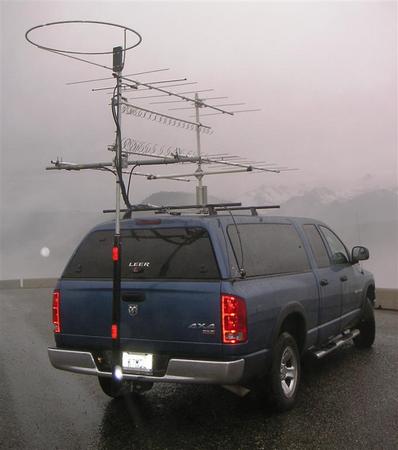
Want a whole lot of antennas? Get a ham ticket and grow one antenna for every band your going to work. Found this pic on the net a while back...Hammers are SERIOUS!
Suddenly the 10K isn't so awe inspiring huh? 
Hank~CEF559
Northeast Net Control
Eastern Long Island NY
|
Jameslarson
Intermediate Member
Username: Jameslarson
Post Number: 296
Registered: 4-2006
| | Posted on Friday, April 06, 2007 - 2:22 pm: |
|
Foldover mounts. Very interesting. Or maybe some quick release. OK, so let's see. The reflector gets mounted in the rear. Center pin grounded.
The driven element is next, coax installed normal. Then after that are my 4 directors. also center pin grounded correct?
I suppose now all I have to figure out is the spacing inbetween each antenna, and the height of each antenna. Once I find this out, I am going to do it. I promise. May not get done in one sitting, but I will do it. If anyoen has that informatin, let me know. Thanks. |
Dale
Advanced Member
Username: Dale
Post Number: 727
Registered: 12-2002
| | Posted on Friday, April 06, 2007 - 9:11 pm: |
|
omg vanillagorilla what kinda antenna/or antennas is that muliple banded antenna or what
like 6meter
10meter
2meter
11meter
or just 11meter alone
dale/a.k.a.hotrod
cef426
cvc#64
|
Goat373
Intermediate Member
Username: Goat373
Post Number: 340
Registered: 3-2005
| | Posted on Friday, April 06, 2007 - 9:52 pm: |
|
ill have to take a pic of my hamradio mobile...i have 4 antennas on a ford ranger...lol
Brian
CEF574
KI4LXH
"The more you learn...the more you realize how little you know"
|
Vanillagorilla
Advanced Member
Username: Vanillagorilla
Post Number: 981
Registered: 4-2005
| | Posted on Saturday, April 07, 2007 - 8:50 am: |
|
Not sure Dale! Like I said I found this on the internet doing a search on Ham radio to feed a thirst for knowledge . There was everything from this truck to others as well as a few SMALL imports set up similar. If I can find the link I'll send it off to you. Looks like this guy is covering a WHOLE LOT! Yagi's / halo and slinkys oh my!
I wonder how often the kids in the nieghborhood shoot hoops behind it!
When I went for my exams earlier this week there was a ford exploder sitting in the lot set up with what looked like a 2mtr yagi and a halo.
Brian....I've referred to you as a sick monkey more than once. Nothing would surprise me  ...but I'd love to see it anyway! ...but I'd love to see it anyway!
Hank~CEF559
Northeast Net Control
Eastern Long Island NY
|
Patzerozero
Senior Member
Username: Patzerozero
Post Number: 3595
Registered: 7-2004

| | Posted on Saturday, April 07, 2007 - 3:18 pm: |
|
the loop is 6m, the beam on top 2m, beam on bottom 222 mHz, the bigger coil 900 & the smaller 1.2 ghz? just a guess. then, by judging from the mountains in the background, he's probably between 1 & 2 miles HIGH, so antenna size is of minimal importance!
james, you SHOULD be able to get 3 elements using predators on your vans roof. more length will require extensions. a 3 element beam will get you 3 db of gain, but, you are using shortened 1/4 wave antennas, so, you won't even get that. remember, 3 db of gain is like doubling your power & getting maybe 1/2 S-unit of signal increase. for talking DX, especially while moving, it probably isn't worth the effort. THEN, consider you are making things directive to the FRONT. so, everytime you head EAST on the LIE, you are almost cutting your signal strength in HALF to DX stations in say, indiana, & mudduck 18 wheelers with their crummy palomar amps will be keying over you! if you want to double your output, in a mobile, you're better off doubling your amplifier. you should have absolutely no trouble getting out most of the time during the upcoming spring E skip season the way you are set up. if you have any problems, you should go over what you have, because it is all 'good stuff' you're running. |
Jameslarson
Intermediate Member
Username: Jameslarson
Post Number: 299
Registered: 4-2006
| | Posted on Sunday, April 08, 2007 - 11:19 am: |
|
Yes, I suppose I could always double the amp, etc... But this is more of a project thing for me just to do you know. How would I get extensions? What could I use for say 4 antennas? The directors get center pin grounded? So does the reflector? I am confused on that because one site I saw said NOT to gorund the directors. Also, I need to know disctances between each antenna, and length of each antenna. Again, this is more of a project than anything else. And I would love to try it and use it. Thanks. |
Kid_vicious
Senior Member
Username: Kid_vicious
Post Number: 2475
Registered: 9-2004
| | Posted on Monday, April 09, 2007 - 8:44 pm: |
|
james, the lengths will be determined by a formula.
look online for antenna formulas for yagi type beam antennas.
there is a general rule that is applied for the distances between directors and reflectors and driven elements, and playing with this distance relationship will yeild increases in gain that correspond with decreases in front to back ratio, and vice versa.
sort of something that has to be "optimized" by experimentation.
find the formulas, apply them, and adjust from there. might want to clamp antennas in place before mounting or something like that.
maybe you could attatch a long piece of aluminum tubing to the gutter of the van and use that as your boom. with antennas going up from it.
good luck,
matt
anyone wanting a "clean signal", just look to the left and build one of these!!!
|
Dale
Advanced Member
Username: Dale
Post Number: 741
Registered: 12-2002
| | Posted on Monday, April 09, 2007 - 9:54 pm: |
|
ive never done this but seen online what hes taliking about.im just wondering if hell have enough room for four with proper spacing
dale/a.k.a.hotrod
cef426
cvc#64
|
Jameslarson
Intermediate Member
Username: Jameslarson
Post Number: 305
Registered: 4-2006
| | Posted on Tuesday, April 10, 2007 - 9:28 am: |
|
Kid, thanks for the info. I am still confused on one point here though. Do I ground the center pins on the directors or not? What about the reflectors? Some of my research is telling me NOT to ground the directors. But that does not make sense. Let me know. Thanks. |
Kid_vicious
Senior Member
Username: Kid_vicious
Post Number: 2478
Registered: 9-2004
| | Posted on Tuesday, April 10, 2007 - 4:20 pm: |
|
sure thing james,
im not the most informed person on beam antennas, but from what i understand; the driven element is isolated from the boom, and the rest of the elements are attatched to it with a direct electrical connection.
so, yes, ground the center pins on all antennas except the driven element.
think of it this way; the other antennas are considered "parasitic" elements, meaning that they radiate their signal by getting it from the driven element. (i know there are 1,000 better ways to say that, but...)
so the driven element is your standard "dipole" antenna, and the rest of the elements, or in your case "antennas", just direct or reflect the signal that the driven element creates.
thats where the gain and directivity come from, the parasitic elements.
what you are building is the top half of a 1/2 wave vertical yagi beam antenna.
your van is the boom, the antennas are the elements.
copper reomved some of my post, so i'll just email it to you.
matt
anyone wanting a "clean signal", just look to the left and build one of these!!!
|
Chrisbama351
Junior Member
Username: Chrisbama351
Post Number: 14
Registered: 2-2018
| | Posted on Sunday, November 27, 2022 - 5:25 am: |
|
I wanna see What You did.
There are a lot of ways to design it.
55 antenna magic is what I think it is?
With a van I could see 4 ss 102" down the center, 2 driven with a director isolated and reflector grounded.
ala"Bama" 351 in Colorado |

